Bipolar Power Supply Build Guide
The assembly of the power supply will begin with the parts with the lowest profile, and continue to the larger profile parts. The two power resistors [R01, R02] will be omitted until the final step, so that the positive and negative regulators can be tested individually. Be very mindful of parts that have polarity, such as electrolytic capacitors and diodes. Reversing polarities can be dangerous and cause damage. We recommend using high quality silver bearing solder, and cleaning any remaining flux off of the contacts. Flux is conductive, and can cause problems if boards are not properly cleaned. We use Kester solder with water soluble flux that can be washed off with water [part number: 24-7068-6403]. If you don’t use solder with water soluble flux, the boards can be cleaned with isopropyl alcohol and Q-tips. Be very careful handling high voltage AC in this project, it can be very dangerous.
If you have any questions while building your kit, you can reach out to us for support: mark@hamptone.com
PCB Assembly:
STEP 1: RESISTORS

Populate and solder all 1/4 watt resistors: R3, R4, R5, R6. Use a multimeter to determine the values of resistance.
STEP 2: DIODES

Populate and solder diodes D01, D02, D03, D04, D05, D06. Remember that diodes have a polarity, and the white stripe printed on the circuit board must match the direction of the grey stripe on the part. Save the cut leads for test points.
STEP 3: TEST POINTS

Use your saved cut diode leads to form hoops for test points. Solder them in place in the locations labeled: POSIN, NEGIN, GNDTP, GNDTP2, POSTP, NEGTP.
STEP 4: CAPACITORS

Populate and solder capacitors: C1, C2, C9, C10, C13, C14. These capacitors have no polarity.
STEP 5: TRIM POTS

Populate and solder trim pots: R07, R08.
STEP 6: ELECTROLYTIC CAPACITORS

Populate and solder electrolytic capacitors C03, C04, C05, C06, C7, C8, C11, C12. These capacitors have a polarity. Take special care to install these capacitors according to the polarity markings printed on the circuit board. If they are installed backwards, they can explode and cause damage when the unit is powered up. Be very careful!
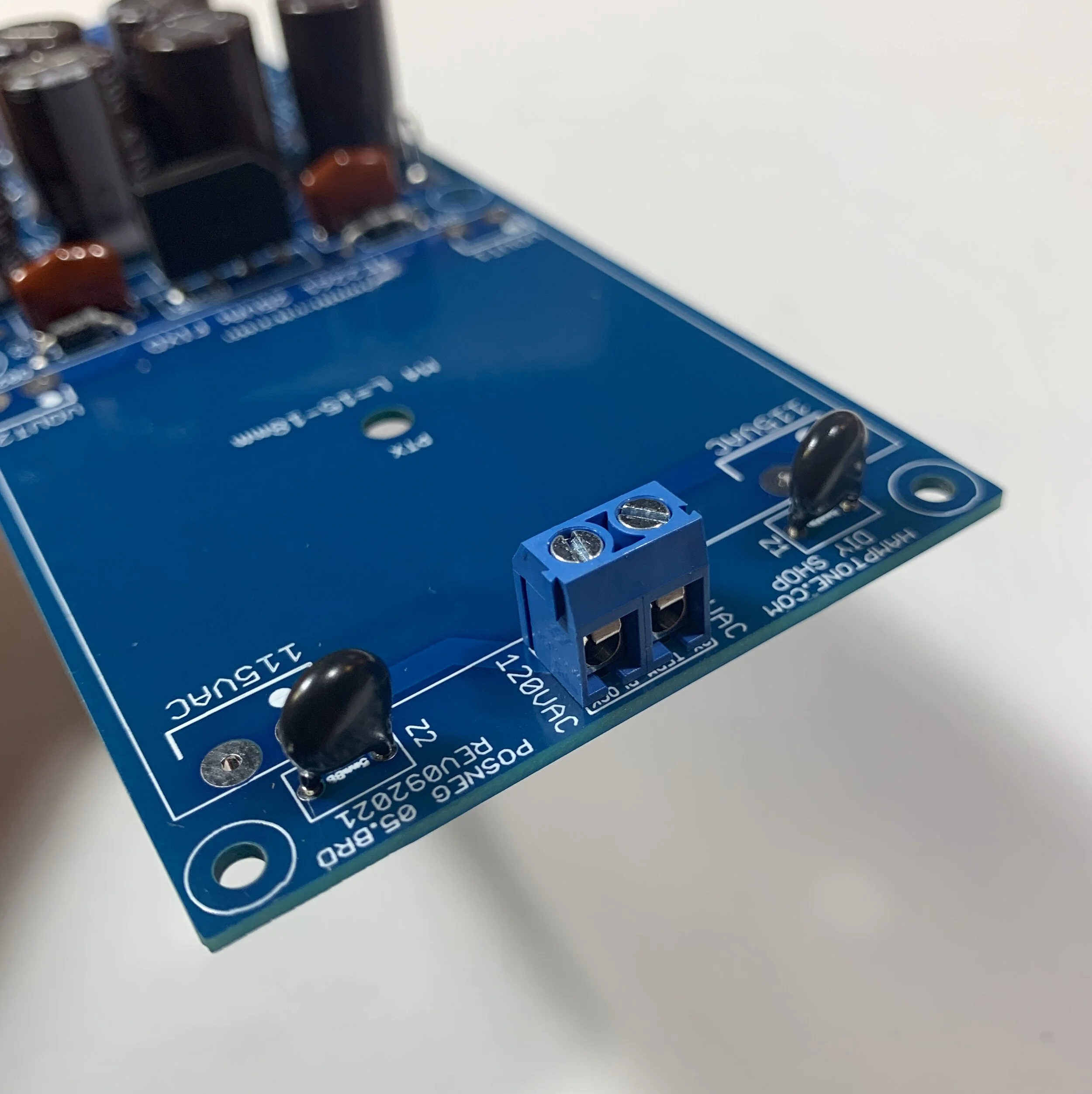
STEP 8: TERMINALS
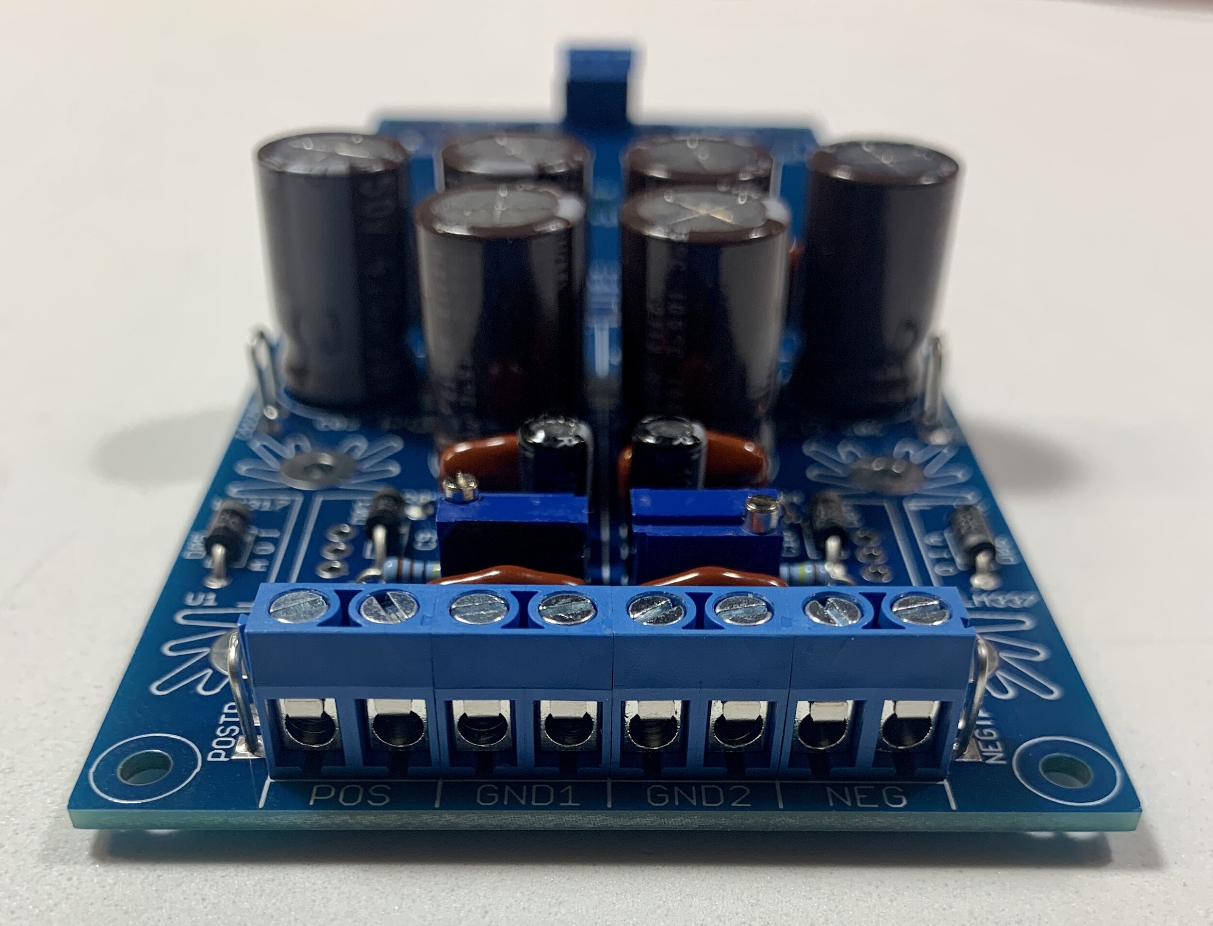
The terminals connect together by sliding them side by side. First combine 4 of them together to form the front row. Then solder the entire block of the 4 of them together into the positions POS, GND1, GND2, NEG. Next, install the last terminal by itself to the ACIN position on the opposite end.
STEP 9: BRIDGE RECTIFIER

Populate and solder in bridge rectifier: B1. This rectifier has a polarity. Match the pin markings on the side of the rectifier with the positive/negative marking on the circuit board pads. Mixing this up will cause damage!
STEP 10: VOLT SUPPRESSORS
Populate and solder volt suppressors: Z1, Z2. These parts have no polarity.
STEP 12: HEATSINKS

Populate and solder big fin heatsinks. Since these parts are made to dissipate heat, using a solder with a lower melting point, such as rosin core, makes soldering them easier. Be sure to install them straight and flush to the board.
STEP 13: VOLTAGE REGULATORS


There are two different regulators, the LM317 is for the positive side and the LM337 is for the negative side [follow printing on board]. The regulators will be mounted to the heatsinks with the provided collection of isolation hardware. The hardware is assembled in the order shown in the picture. Assemble this hardware with an end wrench or pliers holding the nut on the inside, using a screwdriver on the opposite side. After the screws are securely fastened, solder them in place.
STEP 14: POWER TRANSFORMER


Insert the power transformer into the pads, it is “keyed” and will only fit in the correct orientation. Use the large bolt to screw through the board to anchor it down. Then solder in place, making sure that it is flush and straight.
Notes on Testing:
At this point the only remaining parts that are not populated should be power resistors R01 and R02. These have been intentionally omitted until the last step, so that the two channels can be connected and safely tested individually. For this step, we recommend wiring the AC power entry through a switch and a fuse for safety. Be very careful, as high voltage AC wall power can be very dangerous. We also recommend using a variac if available, to bring up the AC voltage slowly.
STEP 15: POWER RESISTOR

Bend the power resistor leads and solder it in place to R01. Keep the leads as long as possible and elevate the resistor off of the board. This detail is essential for proper thermal management.
STEP 16: CLEANING

Clean all the pads on the bottom of the board with isopropyl alcohol and Q-tips. If you used solder with water soluble flux, then the bottom of the board can be carefully washed with water and a toothbrush. Be sure that the board is FULLY dry and clean on both sides before continuing to any testing. We use an air compressor to thoroughly dry them.
Positive Regulator Test:
Set your multimeter to DC volts.
Connect the positive lead to POSTP test point, and connect your common lead to the GNDTP2 test point.
Connect your AC input through your fused power entry wiring to the ACIN terminals on the power supply board. Make sure that the switch is off and/or the unit is unplugged before handling these connections, they are dangerous.
Bring up the AC power slowly with a variac and monitor the DC voltage from the regulator output as it rises.
Trim the POS ADJ [R07] trim pot to adjust to the desired voltage.
Be sure to turn off or disconnect the AC power before handling the unit again. BE VERY CAREFUL.
STEP 17: POWER RESISTOR

Bend the power resistor and solder it in place to R02. Keep the leads as long as possible and elevate the resistor off of the board. This detail is essential for proper thermal management. Clean the pads with isopropyl alcohol. This step connects the negative regulator circuit.
Negative Regulator Test:
Set your multimeter to DC volts.
Connect the positive lead to NEGTP test point, and connect your common lead to the GNDTP test point.
Connect your AC input through your fused power entry wiring to the ACIN terminals on the power supply board.
Bring up the AC power slowly with a variac and monitor the negative DC voltage from the regulator output as it rises.
Trim the NEG ADJ [R08] trim pot to adjust to the desired negative voltage.